
Drilling and Coring Bits
1.1 Roller Bits and Blade Drag Bits
1.1.1 Size
Roller bits shall be furnished with sizes as specified on the purchase order. Blade drag bits shall be furnished in
the sizes specified on the purchase order.
NOTE
See API 7G for commonly used sizes for roller bits.
1.1.2 Tolerances
The gauge diameter of the cutting edge of the bit shall conform to the OD tolerances specified in Table C.26
(Table D.26).
1.1.3 Connections
Roller bits shall be furnished in the size and style of the pin connection shown in Table C.27 (Table D.27). Blade
drag bits shall be furnished with the size and style of connection shown in Table C.28 (Table D.28) and shall be
pin or box.
1.1.4 Marking
Bits shall be die-stamped in some location other than the make-up shoulder with the following information:
a) manufacturer’s name or identification mark,
b) the bit size,
c) “API 7-1”;
d) the size and style of connection.
EXAMPLE—A 200 mm (7-7 / 8 in.) bit with 4-
1
/ 2 REG rotary shouldered connection is stamped as follows:
— AB Co. (or mark) 200, API 7-1, 4-
1
/ 2 REG; or
— AB Co. (or mark) 7.87, API 7-1, 4-
1
/ 2 REG.
1.2 Diamond Drilling Bits, Diamond Core Bits, Polycrystalline Diamond Compact (PDC) Bits
1.2.1 Diamond Bit Tolerances
Diamond drilling bits, diamond core bits, and polycrystalline diamond compact (PDC) bits shall be subject to the
OD tolerances shown in Table C.29 (Table D.29).
1.2.2 Diamond Drilling Bit and PDC Bit Connections
Diamond drilling bits and PDC bits shall be furnished with the size and style pin connection shown in Table C.30
(Table D.30). All connection threads shall be right-hand.
Because of their proprietary nature, the connections on diamond core bits are not shown.
51
Rotary Drill Stem Elements1.2.3 Diamond Bit and PDC Bit Gauging
1.2.3.1 General
All diamond and PDC bits shall have the outer diameter inspected using the dimensional guidelines for ring
gauges given in 10.2.3.2 and 10.2.3.3.
1.2.3.2 Gauge Specification
“Go” and “no-go” gauges shall be fabricated as shown in Figure 14 and as described below.
a) “Go” and “no-go” gauges shall be a ring fabricated from steel plate 25.4 mm (1 in.) thick with OD equal to the
nominal bit size plus 38.1 mm (1-1 / 2 in.).
b) The “go” gauge ID shall equal the nominal bit size plus 0.05 mm (0.002 in.) clearance, with a tolerance of
+0.08
/ 0 mm (
+0.003
/ 0 in.).
c) The “no-go” gauge ID shall equal the minimum bit size (nominal size less maximum negative t o l e r a n c e )
minus 0.05 mm (0.002 in.) interference, with a tolerance of
0
/ -0.08 mm (
0
/ -0.003 in.).
1.2.3.3 Gauging Practice
The “go” and “no-go” gauges shall be used as follows.
a) If acceptable, the product bit shall enter the “go” gauge (product not too large).
b) If acceptable, the product bit shall not enter the “no go” gauge (product not too small).
c) For accurate measurement, the temperature of both the “go” and “no-go” gauges shall be within 11 °C
(20 °F) of the temperature of the bit or core-head.
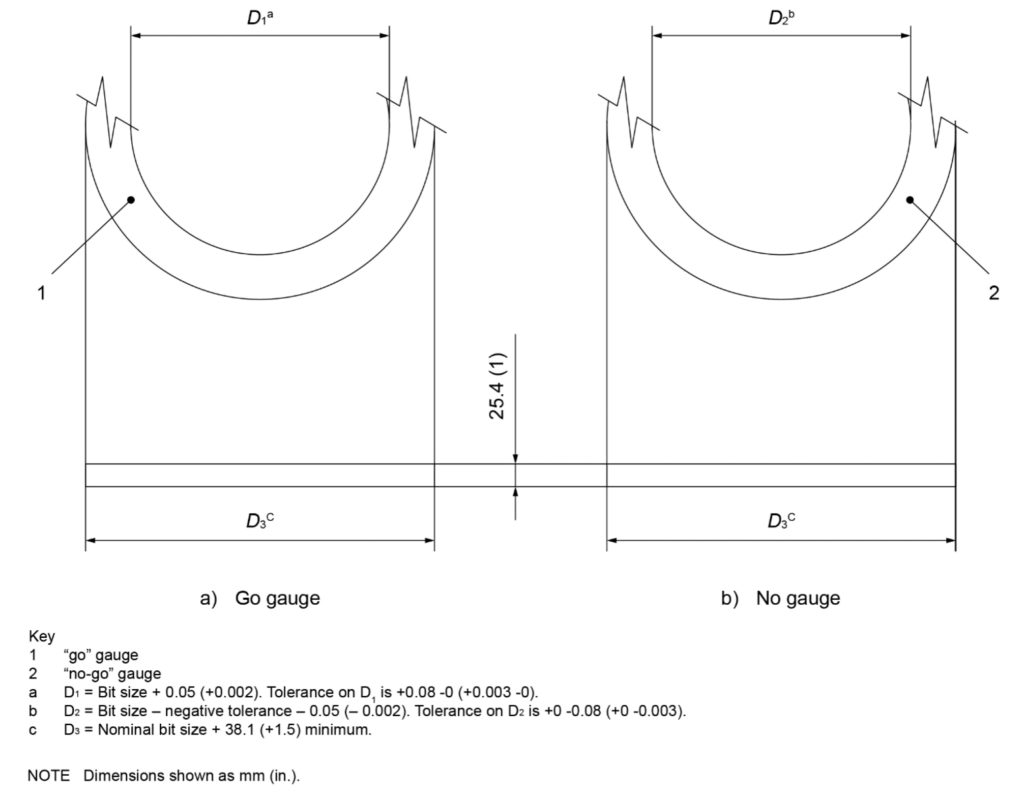
Figure 14—Gauge Dimensions for Diamond and PDC Bits
1.2.4 Marking
Diamond drilling bits and PDC bits shall be permanently and legibly identified in some location other than the
make-up shoulder with the following information:
a) the manufacturer’s name or identification mark;
b) the bit size;
c) “API 7-1”;
d) the size and style of connection.
EXAMPLE—A 190.5 mm (7-1 / 2 in.) bit with a 4-
1
/ 2 REG rotary connection is stamped as follows:
— AB Co. (or mark), 190.5, API 7-1, 4-
1
/ 2 REG; or
— AB Co. (or mark), 7.5, API 7-1, 4-
1
/ 2 REG.
Diamond core bits shall be permanently and legibly identified by die-stamping on some location other than the
make-up shoulder with the manufacturer’s name or identification mark and “API 7-1” as follows:
— AB Co. (or mark), API 7-1
Because of their proprietary nature, the connections on diamond core bits are not shown. The marking “API 7-1”
shall indicate that the other dimensional requirements of this standard have been met.
53
Rotary Drill Stem Elements10.3 Fixed Cutter Bits—Supplementary Requirements
1.3.1 General
This section describes supplementary requirements for fixed cutter bits that may be specified by the purchaser
or agreed between purchaser and manufacturer. These requirements apply only when stated on the purchase
agreement. These requirements are only applicable to polycrystalline diamond compact bits and diamond drilling
bits. They do not apply to diamond core bits.
NOTE
These supplemental requirements are designed to mitigate fatigue crack failures that occurred in the pin
connections of small diameter (≤ 6-3 / 4 in. OD) fixed cutter bits; even though these requirements may be specified for any
diameter bit size, they may not be as beneficial on larger diameter (> 6-3 / 4 in. OD) bits.
1.3.2 Supplementary Requirement 1 (SR1)—Gall-resistant Treatment of Threads and Sealing Shoulders
1.3.2.1 SR1 General Information
A gall-resistant treatment of zinc phosphate or manganese or zinc-and-manganese phosphate shall be applied to
the threads and sealing shoulders of the bit’s pin connection, or box connection if supplied with a box connection.
Application of the treatment shall be after completion of all gauging. The treatment type shall be at the discretion
of the manufacturer.
1.3.2.2 SR1 Marking
Bits treated to the requirements of SR1 shall be marked with “SR1” in addition to the marking requirements
specified in 10.2.4.
1.3.3 Supplementary Requirement 2 (SR2)—Cold Rolling of Thread Roots
1.3.3.1 SR2 General Information
The thread roots shall be cold rolled. As with stress relief features, laboratory fatigue tests and tests under actual
service conditions have demonstrated the beneficial effects of cold rolling the thread roots of rotary shouldered
connections. Application of the cold rolling shall be after completion of connection gauging as in accordance
with API 7-2.
Gauge standoff will change after cold rolling of the threads and may result in connections that do not fall within
the specified gauge standoff if gauged after cold rolling. This will not affect the interchangeability of connections
and will improve connection performance. It is therefore permissible for a connection to be marked as complying
with the requirements of API 7-2 if it meets the standoff requirements before cold rolling. In such event, the
connection shall be stamped with a circle enclosing “CW” to indicate cold rolling after gauging. The mark shall be
located on the connection as follows:
a) Pin connection—at the small end of the pin,
b) Box connection—in the counterbore.
1.3.3.2 SR2 Marking
Bits treated to the requirements of SR2 shall be marked with “SR2” in addition to the marking requirements
specified in 10.2.4.
54
API Specification 7-1 10.3.4 Supplementary Requirement 3 (SR3)—Stress-relief Features
1.3.4.1 SR3 General Information
Stress-relief features shall be added to bit connections 4-1 / 2 REG and larger. The surfaces of stress-relief features
shall be free of stress risers such as tool marks and steel stencil impressions. The stress-relief features shall
conform to the dimensions specified in API 7-2.
Laboratory fatigue tests and tests under actual service conditions have demonstrated the beneficial effects of
stress-relief contours at the pin shoulder and at the base of the box thread. Stress-relief features are of two basic
designs: a groove on the pin and a boreback contour for boxes, or a groove on both the pins and boxes. The
boreback design is the recommended relief feature for box connections. However, the box relief groove has also
been shown to provide beneficial effects. It may be used as an alternative to the boreback design.
Stress-relief features cause a slight reduction in the tensile strength of the pin and the section modulus of the
connection. However, under most conditions the reduction in cross-sectional area is more than offset by the
reduction in fatigue failures. If unusually high tensile loads are expected, calculations of the effect should be
made.
1.3.4.2 SR3 Marking
Bits treated to the requirements of SR3 shall be marked with “SR3” in addition to the marking requirements
specified in 10.2.4.
1.3.5 Supplementary Requirement 4 (SR4)—Non-destructive Examination
1.3.5.1 SR4 General Information
All bit connections, after threading and any heat treating, shall be inspected via bi-directional wet fluorescent
residual magnetic particle method for longitudinal and transverse imperfections/cracks both on the inside and
outside surfaces in accordance with ASTM E3024. Internal surfaces of connections with ID bores 50.8 mm
(2 in.) in diameter or smaller are exempt from this requirement. Inspection shall include the stress relief features.
Outside inspection shall include the entire connection thread area from pin end or box end shoulder, up to and
including the bit shank area. Evaluate all crack-like indications to verify that they are cracks. All bits found to have
cracks shall be rejected.
1.3.5.2 SR4 Marking
Bits treated to the requirements of SR4 shall be marked with “SR4” in addition to the marking requirements
specified in 10.2.4.
1.3.6 Supplementary Requirement 5 (SR5)—Make-up Torque
The manufacturer shall provide the recommended make-up torque for any bit manufactured to these supplementary
requirements (SR1 to SR4).